- Home
- Home_de
- Products
- Downloads
- Forum
- Sales
- News
- Exhibitions
- Know how
- Building VP-2500D workingtable
- First installation
- VP-2500D 0402 placement test
- Mark detection demo
- Placing TQFP48 demo
- 0201 Placement
- BGA Alignment
- FAQ-Feeder-settings
- Soldering-FAQ
- Controller Upgrade V1 to V2
- How to upgrade to 19 slot nozzle changer
- First setup and placement job
- How to build Electronics
- For Makers
- Questions & Answers
- Software
- Repair Documents
- References
- Service
- Spare-Parts
- Videos
- Warranty
- Kompetenz
- Competence
- Cookie Policy
- Privacy Policy
- About
- PANDA-design-contest
- New V3 software

V2 Vision Placer PC SOFTWARE for pick and place machine
PC requirements:
The Vision Placer software is based on Microsoft Dot Net and runs on Windows 7, 8, 10.
Our recommend configuration is a PC having I3 processor based PC and minimum 4Gb RAM for best performance.
If you use slower PC the vision system performance drops and the machine slows down.
A dual core Atom processor should be ok for mid speed use. (normal case!)
HD Camera setup needed for Raptor, Pecker, VP-2800HP-CL64-4R / RCV
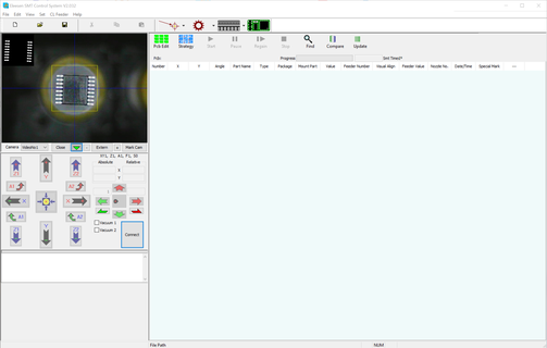
Vision Placer main window part list view

Main interface of VP2X00D machine controller software system showing loaded placement job. Mount state can be changed on one mouse click. Multiple lines can be selected and changed in a single dialog.
Vision Placer main window feeder list view

Feeder List of VP2X00D
All feeder types where shown in one grid.
The feeder settings have templates in package database
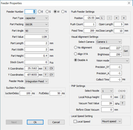
Vision Placer feeder editor window you open by double clicking a feeder line in the grid view

Feeder dialog to setup position and properties for each feeder line.
Here will be the nozzle assigned and the vision system alignment enabled and adjusted.
The Part remainder counts shows the remaining parts on the spool.
If you choose the feeder mode grid box it is possible to access any position inside the working area as logical feeder.
Vision Placer Grid box setup

Grid box setup for ten pieces in a row can be used for cut strip feeder pickup. It is possible to define a single pick up position for a vibration feeder for example.
This function is used to define any software defined feeder configuration.

Grid box setup for 16 pieces in a tray.
Vision Placer part properties dialog

The coordinates are imported from placement file but can be teached in using the position of top camera by pressing CX and CY button.
The part angle is the placement angle on the board the angle of the part in the feeder will be automatically adjusted.Select Feed assign a feeder line to the position in the placement file.On File import the system tries to assign the feeder by partname automatically.The SMT switch enables the placement.And if the feeder line has visual alignement setup it is possible to disable for the single placed part here.Open Feed>> opens directly the corresponding feeder dialog.
Vision system setup

The visual system use a visiual area for detection and contrast and brigthness setting to receive a clear black and white picture. We set the precision in the camera setup for each bottom camera. Offset correction will be done in one shot!
Angle adjustment need some iterations an can be limited by setting a correction count.
After hitting the "VisionTest" button you receive the vision system view in the left bottom corner of the camera windows.
First set the “Visual W” and “Visual H” to define the visual area. The visual area size was set to 10 x 10mm in this example! You can use the right click menu option “Pick to Visual Camera” in our feeder grid to carry a part to bottom camera.
We adjust Contrast and Brightness until we receive a clean BW picture after hitting the “VisionTest” button. You receive different results by adjusting the parameters. The first one is a good result and on the second you need to improve the contrast setting!
The next example show full body alignment but now we should prefer to adjust vision parameters to do pin based alignment like shown in pictures above.

The vision system setting can be saved for each feeder line.
We need to adjust contrast and brigthness because the parts have different color and surface.
Our vision system is very fast and accurate but you should know we can't recognize the part and we can't detect pin 1!
The big advantage is you have no problems for setup and the system does what it is designed for adjust angle and offset.
Vision Placer recommend fiducial design parameters

This is a recommend Fiducial design.
You can use 1.0mm, 1.5mm, 2mm mid pad for detection!
But don't forget the solder mask opening around!
It is now possible to use a cross or other shapes to align by setting the invert image switch in basic settings.
But a round fiducial receive much better results.
We can adjust contrast and brightness for both mark points together or separate if the environment conditions are different for second mark point.
Placement strategy settings include now height sorting in V2 controller software!

Nozzle Management list for automatic nozzle changer

The standard nozzle changer has 6 positions on HP and DP machines and 4 nozzles on S machine.
Package database for fast editing feeder settings

Our Feeder setup need a lot of different parameters but we use maybe a lot of similar parts.
The solution is we offer the package database where footprint name can be defined and all placement specific parameters can be stored.
If you use the footprint in a feeder setup you are able to automatically copy all of the package database settings to the feeder properties. The next nice function is to automatically update all feeder when you change a single part in the part database and enable the update function before you save the changed properties.
All Feeder having the same footprint will be updated.
Think about to define different footprints for different part types or height. So you are able to switch visual alignment for a group of parts of or on, change the vision parameters or simply only the height settings.
New Vision Function starting from V2.031

The feeder editor has new parameter to select the vision model. "FootEdge4" is for a retangular package like TQFP.


